Frequently Asked Questions

Contents

Why wood

The basic raw material in most AEROBAT propellers is beech wood (Fagus sylvatica), due to the straight, long fibres of trees up to forty metres high, with PEFC European eco-certificates guaranteeing that the forests where it comes from are sustainably managed. FSC certified sustainable forest.

The wood is cut, dried and stabilised specially for our purposes.

The beechwood laminates, between 10 and 15 millimeters thick, are joined together to form specific blocks for each job, paying careful attention to the shape and direction of the grain, the direction of rotation and the future specific design of each propeller.

Unlike other, artificial, materials, wood does not suffer structural fatigue under different tensile stresses, flexion and centrifugal force during the working of the propeller, because its fibres are just interlaced each other without forming more or less rigid crystals, as happens with metal alloys or synthetic resins, that crack with fatigue, causing fissures to appear in the former, and elastic properties to change in the latter. Wooden propellers are the only ones which have no life limit in terms of hours of operation.

The versatility which this noble material, wood, offers us, not being subject to using moulds, the experience gained in over twenty-five year’s history of AEROBAT and the assistance of new technologies, allow us to adapt to the demands of any propeller for any engine.

In the manufacturing process we hardly generate any waste. The chips from the machines are collected and compressed automatically for use as biomass briquettes, solid fuel, with a high calorific value.

Designation

On the propeller are engraved some numbers and letters for their correct identification, it is their reference that tells us the following:

49 35 P R K

49 Propeller diameter, inches.

35 Propeller Pitch, inches.

P Design reference.

R Turning direction, R right L left. Seen in the direction of the flight.

K Mounting bolt holes.

Installation Torque

Diameter of Bolts mm / inches Tightening Torque Nm / inlb
M6 / 1/4″  9 – 10 / 75
 M8 / 5/16″  15 – 17 / 140
 M10 / 3/8″  23 – 25 / 300

The above table can be used, but the best way of tightening a wooden propeller is to use your common sense (observation and a bit of care using the Allen key or spanner). The tightening torque required varies according to various factors such as the number of bolts, their size and thread, the total surface of the plates (propeller plate and rear plate), hardness of the wood, etc… “Torque” spanners have a very long handle and you will hardly note any effort in reaching the final tightening; just use their scale as a guide.

NB: the bolts MUST be DRY (no oil).

Tightening Procedure

Assemble the parts and hand tighten the bolts. Then use your spanner to give each bolt two or three turns at a time moving from bolt to bolt in a star pattern (going from one bolt to the one diagonally opposite, and then the next diagonally opposed pair); you will note that the consistency (the force needed to tighten) increases with each step and you MUST stop when this consistency suddenly gets solid, and always before chaffing the wood. The metal parts should mark the varnish, but not sink in.

If the bolts have not been touched for a long time, they should be checked with the flat spanner or Allen key to ensure that they are still at the final consistency explained above. This should be done especially at the beginning of the dry season (end of spring) and then once again once summer has set in.

When a new propeller has been installed for the first time, the tightening must be checked after the first 6 to 10 hours of use.

TRACKING adjustment:

When the propeller spins, the tips should pass through the same point with a maximum deviation of 3 mm. To make an adjustment of 1 to 2 mm you can intentionally reduce the tightening of the bolts beside one of the blades, and then excessively tighten the opposite bolts. You must then tighten the first bolts (which will have loosened slightly) back to the “normal” tightening position.

Installation of a double propeller:

In the following picture you can see the correct way to mount the two 2-blades which make up a double or 4-blade propeller. You must match the two letters which indicate the correct position, the 2-blade engraved with letter “A” which goes next to the engine, and that marked “B” on the outside.

You must also fit a washer between each bolt head and the mounting plate.

Obviously, in addition to a correct mounting (tracking & tightening), the propeller needs proper maintenance. Just the remains of dead insects on the propeller surface cause the engine’s maximum RPM to increase by about 50 revolutions, and performance to drop slightly.

Maintenance

The maintenance of the propeller is fundamental for good performance.

The propeller is one of the most important elements to be borne in mind for the pre-flight check list. You must look out for both any possible impacts by objects during any phase of the previous flight and the cleanness of the propeller.

Use a cloth, lightly soaked in soapy water, to remove stains and any remains of insects caught during use and which would noticeably reduce performance.

If the propeller is very stained with oil, you can spray it with an ovencleaner and, once clean, rinse it with water and dry it off with a cloth.

All impacts must be sealed and filled to surface level of the blade with epoxy or (much easier and quicker) with cyanoacrylate and bicarbonate (on the shielding) or cyanoacrylate and powdered wood and bicarbonate on the rest of the surface.

When your spare propeller is not in use, it is advisable to wrap it up and store it horizontally in a dry place which is not subject to excessively high temperatures.

Any important repairs must be carried out with a total guarantee of perfect performance, and ensuring that the picth of both blades is correct and that they are properly balanced.

3 blade best

An adjustable pitch 3-blade propeller has certain advantages over a fixed pitch 2-blade propeller, but also a few disadvantages.

Amongst the advantages we can point out:

.It is more versatile, as you have the possibility of adjusting the pitch to suite your personal requirements, such as improving impulse for take-off or reducing consumption at cruising speed, etc.

.It is equivalent to a larger 2-blade and can be useful for ultralights with limited space for the propeller because it passes near to the ground or the tail tube. This problem can be solved by fitting a 3-blade or 4-blade if space is very limited.

.It works more smoothly and is better balanced (indeed, the majority of aircraft manufactured mount 3-blade propellers). As the masses are better distributed on the propeller hub, the in-flight sensations are much smoother.

On the other hand, there are a few disadvantages:

.The pitch is less “elastic” than with a 2-blade, and they lose performance when speed is increased, especially above 150 Km/h.

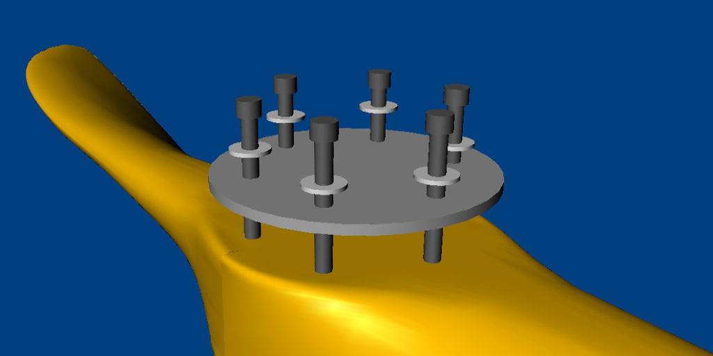
.During the pitch adjustment, when the blades turn not only is the pitch altered, but at the same time it is degraded. All the sections of the blade are turned at the same angle, whereas for a change of pitch the blade should turn a certain angle on the section up to 50% of the blade length, and only half of that angle from here to the propeller tip (100% of the radius).

.There is the risk of adjusting the pitch incorrectly. This would reduce propeller performance.

.In their search for the best possible performance, there are some pilots who make frequent changes without ever finding the best point, either because their objective is unobtainable, or because they make random changes in differing atmospheric conditions, etc.. Only a person with adequate experience and knowledge can achieve success with just a couple of tries, but we can offer the following general advice:

– If there are noise restrictions in your country, this will establish the maximum RPM during take-off without exceeding the maximum allowed noise.

– For the final adjustments you need to measure the maximum RPM during take-off, when the aircraft is moving quickly and about to take off and NOT when the aircraft is stationary.

– Normally the possible adjustments of RPM during take-off will be within 10% below the nominal RPM for maximum engine power. For example, if the maximum engine power is 100 CV at 5,500 RPM, the maximum RPM during take-off should be between 4,900 RPM in aircraft with a long cruising speed of 200 Km/h or more, and 5,400 RPM optimised for short take-offs and climbing.

– Especially in 2 stroke engines it is important that any excessive propeller pitch does not prevent the engine from “breathing” properly, as although it may be possible to make the engine work with 200 – 400 RPM less at cruising speed, if the engine is choked it cannot work well and consequently will consume much more fuel. If this happens, then the plugs will be black when taken out, a sure sign if this has only occurred after the propeller pitch has been increased.

Once you have studied the above, you will be in a position to decide if it is suitable for you to use a variable pitch 3-blade or 4-blade propeller.